Your kit includes: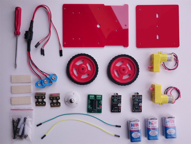
- Double layer robotic chassis
- BO motor (L shape) (2 pcs)
- Wheel (2 pcs)
- Motor driver (1 pcs)
- IR sensor module (2 pcs)
- 9v Battery (3 pcs)
- Battery connector with switch
- Nut-bolt, Screw, Spacer
- Caster (1 pcs)
- Clamp (2 pcs)
- Screw driver
- Foam tape
- 2 female-female jumper wire
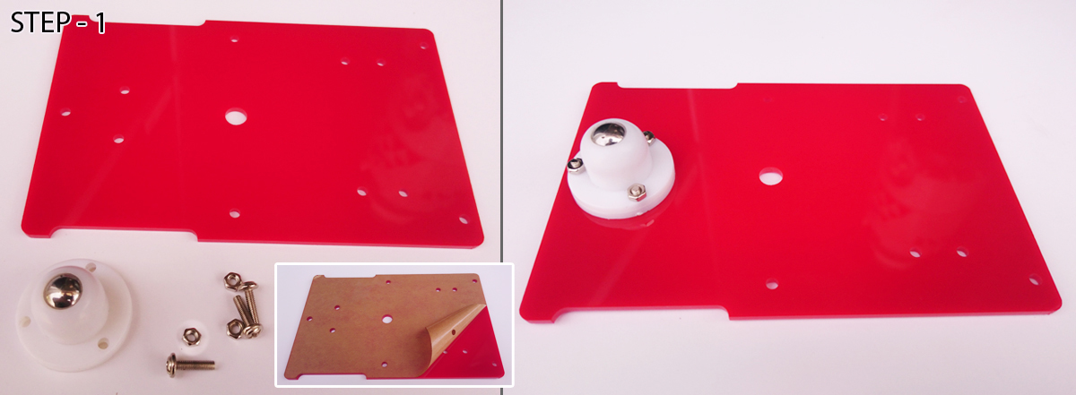
Note: Remove brown protective layer form acrylic parts (If any).
STEP-1: Use 3 nut-bolt to fix caster with base acrylic chassis.
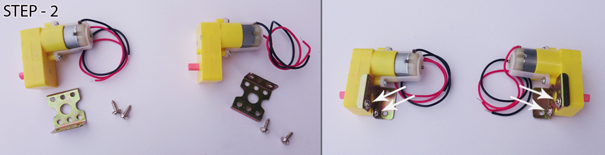
STEP-2: Use 2+2 screw to attach clamp with motors.
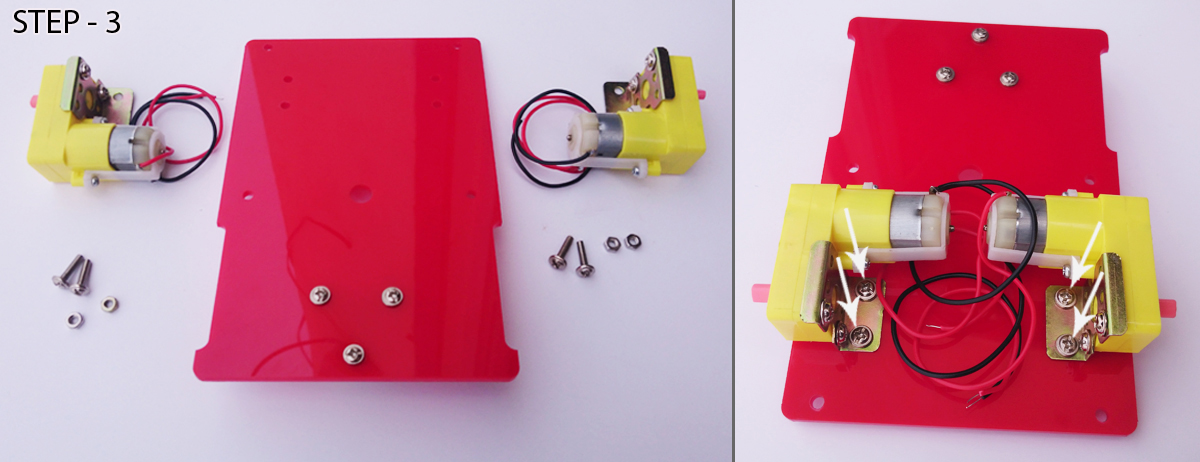
STEP-3: Mount Motor+Clamp with base acrylic chassis using 2+2 nut-bolt.
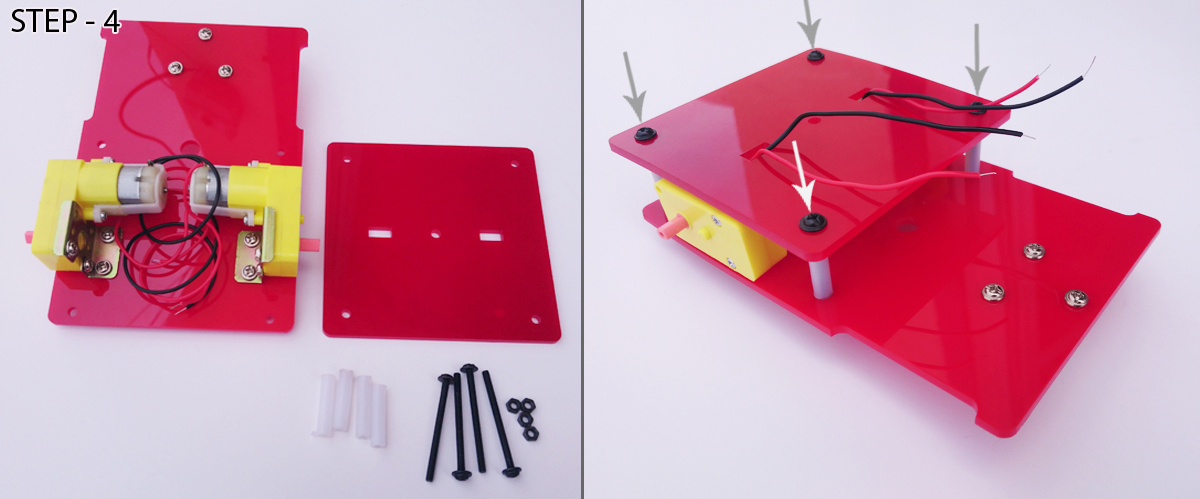
STEP-4: Mount upper acrylic plate with base acrylic chassis using 4 spacer and 4 long nut-bolt.
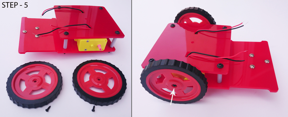
STEP-5: Fix the wheels with motor shaft using 2 small screw.
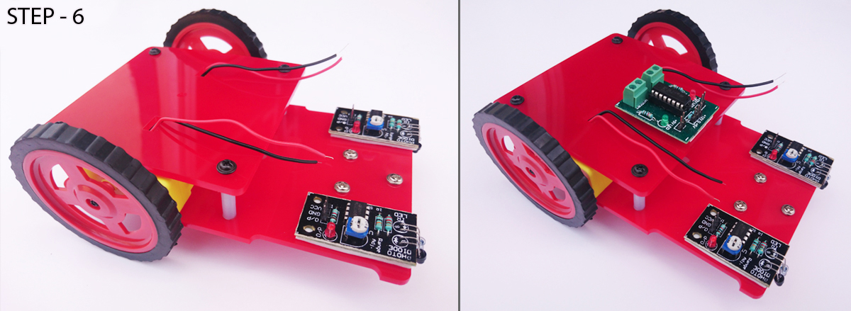
STEP-6: Stick 2 IR sensor in front side of base acrylic chassis and Motor driver on upper acrylic plate.
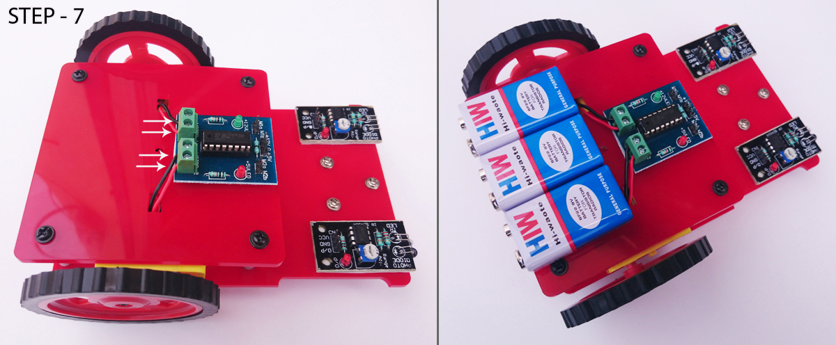
STEP-7: Connect motor wire with motor driver as shown in image and stick 3 batteries on upper acrylic plate.
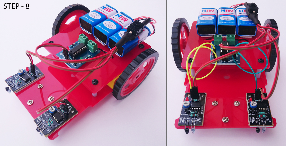
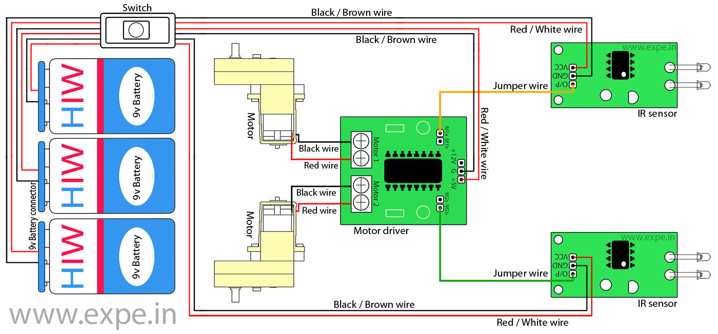
STEP-8: Connect battery connector with 3 batteries. There are 3 Red/White jumper wire and 3 Black/Brown jumper wire at other side of switch, connect these jumper wires as-
Red/White jumper wire with +5v terminal of motor driver.
Black/Brown jumper wire with G terminal of motor driver.
Red/White jumper wire with VCC terminal of IR sensor-1.
Black/Brown jumper wire with GND terminal of IR sensor-1.
Red/White jumper wire with VCC terminal of IR sensor-2.
Black/Brown jumper wire with GND terminal of IR sensor-2.
Connect additional jumper wire with M1a terminal of motor driver and O/P terminal of left side IR sensor.
Connect another jumper wire with M2b terminal of motor driver and O/P terminal of right side IR sensor.
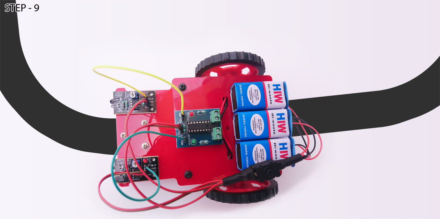
STEP-9: Make a black line (3-4.5 cm) using black tape, put your robot and turn ON the switch.
Troubleshooting:
If the right side wheel+motor rotates in reverse direction then remove the jumper wire from M2b terminal of motor driver and connect it with M2a terminal of motor driver.
Or, If the left side wheel+motor rotates in reverse direction then remove the jumper wire from M1a terminal of motor driver and connect it with M1b terminal of motor driver.
Note: Don’t perform this experiment in direct/partial sun light. Indoor experiment/inside a room is the perfect place for this experiment.